I’ve recently been doing some network restructuring and clean up in order to better separate devices on my network and to remove a bit of the cruft that builds up over time. In the process, I realised I haven’t written about how my smarthome network is structured. My network setup is somewhat different to lots of other setups I’ve seen documented. This is because I’m mostly using Open Source software to drive my firewall and wireless access points.
This article will introduce the technologies I’m using on my network and give you an overview of the structure. It’s not intended to be a full how-to, but I’ll try to include links which will guide you though any parts I don’t cover in detail. Let’s get into it…
What’s special about a Smarthome Network?
The typical smarthome today includes a myriad of devices, probably from a variety of different manufacturers. Obviously, there will be your smarthome devices – smart bulbs, switches, hubs/gateways, vacuums, IP cameras, etc. However, there are all the standard devices too – smartphones, tablets, laptops, desktops, etc. Additionally, it’s likely that there will be some devices specifically used for media consumption.
We can see that there are obviously different classes of devices in the lists above. These differ both in function and in the level of trust that you give to them. It’s this attribute of trust that separates a smarthome network from a standard home network for me.
Consider this, are there any devices on your home network that you maybe don’t trust all that much. What about that light bulb over there? When did it last get a security update? Do you really want that sitting on the same network as the devices you trust with your personal communications, important documents and web searches?
Using existing technologies, we can partition our network in such a way as to separate our trusted and untrusted devices from one another. We don’t need to stop there! We can separate devices that require Internet access from those that don’t or along any other lines that we want. The technologies in question are well trusted and have been around for years: VLANs and inter-network firewalling.
Open Source Components
I’ve been operating a partitioned network setup for some time, pretty much since I got seriously into Home Automation technologies. Recently I’ve seen renewed interest in this is the community. The recent series from Rob at The Hook Up on YouTube was particularly good (part 1, part 2, part 3). A large part of the community appears to be using the Unifi line of products from Ubiquity. I’m not questioning the quality or performance of these products – I’ve never tried them. However, I prefer to use Open Source alternatives where possible.
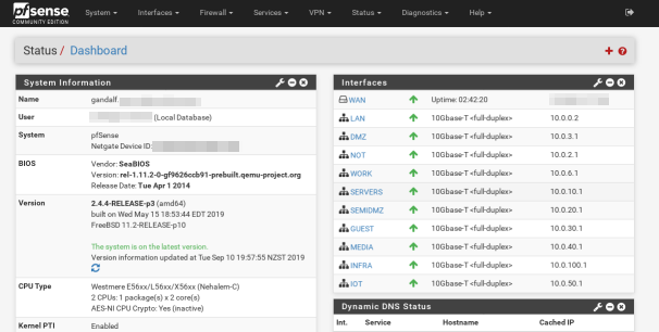
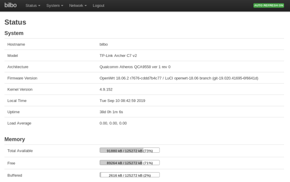
The primary components of my smarthome network are running Open Source software. The first of these is my firewall, running pfSense. The second of these are my wireless access points. For these I use a couple of consumer grade TP-Link wireless routers, running OpenWRT. Since these are running solely as access points and Ethernet switches they don’t suffer performance issues from the consumer hardware. I also don’t put excessive strain on my wireless, preferring to use Ethernet wherever possible.
Unfortunately, there doesn’t appear to be an Open Source OS available for readily available Ethernet switches. As an alternative I’m using a couple of TP-Link switches (the TL-SG1024DE and TL-SG105E). These are great switches for the price. Crucially they come with the VLAN capability that we need for our partitioned smarthome network.
Network Partitioning With VLANs
For those unfamiliar with VLANs, they feel like magic when you discover them! A VLAN is a virtual network, which runs over the top of your physical network cables. Several of these networks can be run over the same connection. This means we can run several networks on the same physical hardware. VLANs work by tagging each Ethernet frame with a network identifier so that the receiving hardware knows which network to send it on to. This usually requires hardware support in your switching hardware, although software support is available in most operating systems.
I subdivide my network into several VLANs, based around both trust and functionality:
- The main LAN network, this houses the trusted client devices (laptops, smartphones, etc). This network has access to most of the others for maintenance purposes.
- The IOT network, which houses smart devices which absolutely require Internet access. At the moment this is just my Smart TV, Neato Botvac and a Chromecast Ultra. The Neato is the only device that uses the associated WLAN. This network is firewalled from all the others but is allowed to access the Internet.
- The NOT (Network of Things – name stolen from The Hook Up video series, linked above). This houses smart devices which are locally controlled, such as my ESPHome devices. Some of the devices on this network (such as my Yeelight bulbs, Milight Gateway and Broadlink RM Mini) want to get out to the Internet but are blocked by the firewall. For ease of use I put the VM hosting my Home Automation services on this network and make an exception for it in the firewall. I’m hoping to change this eventually. This network is blocked both from the other local networks and the Internet, aside from a few exceptions.
- The Media network, this houses all the devices and servers which stream media around my house. This includes both my Kodi systems, an older HDHomerun and the Emby, tvheadend and Mopidy/Snapcast servers. For now the RPi driving my outdoor speakers is living in the NOT network. This is because it’s on wifi and I didn’t want to create another AP for it. Eventually that will be migrated over, once I run a cable into the roof for it. Having the media devices in a separate VLAN should allow me to do some traffic shaping in the future to prioritise their traffic (if needed, I don’t have any problems right now). This network isn’t blocked from any of the others and has Internet access.
- The DMZ, this hosts any services which are available from outside my network. It’s blocked from all local networks, but has Internet access.
- The Guest network, which is tied directly to a specific WLAN only for guest devices. This allows me to provide Internet access to guests without giving them access to anything else. Blocked from all the local networks, but obviously has Internet access.
- The Infrastructure network, this one is new and I’m still migrating devices over to it. The idea is that it will house all the network infrastructure devices, including switches, access points and the physical host servers. Everything in here will have a static IP address. Right now the firewall is open. I will probably lock it down so that admin can only be performed from trusted devices.
- The Servers network, this one is also new and so far empty. Eventually it will contain all the internal server VMs (i.e. non-DMZ, media or HA). The idea is that I can use firewall rules to control access to these from other parts of the network. Most definitely a work in progress.
- The Work network, which houses my company workstation and any other devices used for work, since I work from home. This is blocked from the other networks, except for a few ports. It obviously has Internet access.
Phew… that’s quite a …few(!).
VLANs With pfSense
VLANs with pfSense are fairly easy to configure. It’s basically a two step process:
- Create the VLAN in Interfaces->Assignments->VLANs
- Add a net interface which uses the VLAN in Interfaces->Assignments
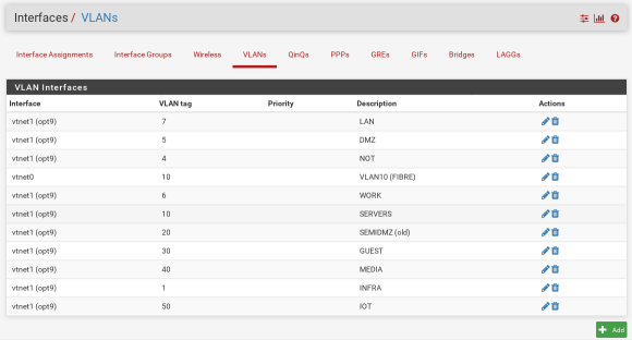
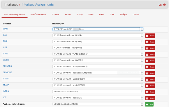
The pfSense documentation gives a better overview of this.
Once your VLANs and interfaces are available you should be able to configure the firewall rules to control traffic between them. You’re probably going to want to block access to the local networks from your secure VLANs and potentially allow Internet access. If you want to also deny Internet access just deny access from that network to all destinations.

OpenWRT: VLANs and Multiple APs
The main reason for using OpenWRT on my wireless APs is to unlock capabilities of the underlying hardware that aren’t available in the stock firmware. Specifically, this will allow you to create multiple wireless access points and assign them to different VLANs.
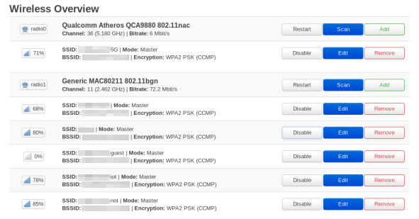
The basic process here is to create a bridge interface. This can be used to group your VLAN and the wireless network together. Adding the VLANs themselves is pretty trivial. There is even a nice GUI editor which shows each port and the corresponding VLANs.
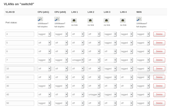
The main gotcha of this setup is to make sure that the dnsmasq service is disabled in System->Startup to prevent it interfering with the DNS and DHCP from the firewall. You can also check the “Ignore Interface” DHCP setting in the interface config for each interface.
You can also delete the default created WAN interface to allow you to use the fifth switch port on the router as another port on the network. This should also disable NATing between the ports which you also don’t need with this setup. Basically, once you are finished tweaking all the settings the device will only act as an access point (for multiple wireless networks) and managed switch.
Special Considerations
There aren’t too many issues that you should run into with this setup, once you get all the pieces into place. There were a few minor things which tripped me up however (two of these are specific to the switch I’m using):
- My TL-SG1024DE switch is a little funny about what VLAN it’s management interface will be available on. It seems like it’s VLAN 1 or nothing. Additionally it adds VLAN 1 as untagged to every port. I eventually just made VLAN 1 into my Infrastructure network to work around this.
- The TL-SG1024DE switch also requires you to set the PVID setting on each port, even if the port will never receive any untagged frames. I just set it to whatever the primary VLAN of the port is.
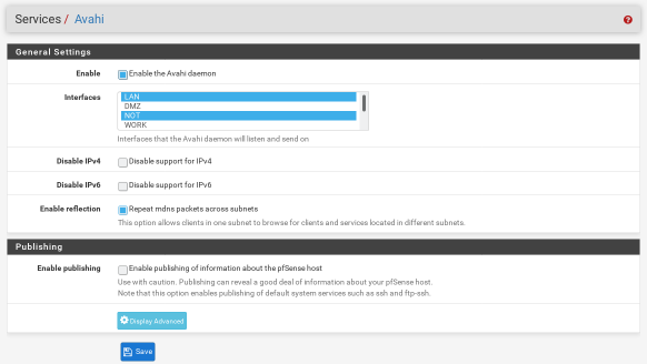
- I held off moving the Chromecast into the IOT network for a long time, since I was worried about the discovery not working across subnets. As it turns out, I shouldn’t have worried. All you have to do is install and enable the Avahi package in pfSense and you’re good to go. This video helped me out, though the settings seem to have been simplified since then (see the screenshot below for my settings).
Core Network and Topology
I’m not going to cover how I setup the main switch on my network, since the purpose of this article is to focus on the Open Source components. Your configuration will also vary depending on what switch you have.
I will say a few words on the physical topology of my smarthome network. My firewall and main switch are located in my ‘rack’. The firewall machine has two network interfaces. One is used as the WAN port and connected to my fibre ONT. The other is the main VLAN trunk to the switch. In my case my pfSense install is actually installed as a virtual machine hosted by Proxmox which runs on the host machine. This is somewhat irrelevant to this discussion and probably deserves a post all of its own.
From the main switch, connections go out to the various rooms in the house. In three of these I have additional switches where I need the extra ports. These are the two OpenWRT devices and the TL-SG105E switch. This layout also gives nice wireless coverage around the house. The uplinks to each of these are configured as VLAN trunks for whichever networks are required at the other end.
Conclusions
Hopefully this post has shown you that it’s possible to create a fully featured and secure smarthome network using Open Source components. I’ve probably glossed over tons of the details of my setup in the process of writing this article. If I put them all in, it would probably be three times as long! If you have any questions, please ask them in the feedback channels. I’m also not a professional network engineer, so feel free to provide improvements and constructive criticism!
My network is a constant work in progress. However, once this latest round of tidying up is complete I think I’ll be in good shape for quite a while. Hopefully this network will happily support all the future projects I have planned for my smarthome!
Leave a Reply