Sometimes it’s nice to be able to undertake a spur of the moment project that can be completed in a couple of hours. Of course, this rarely happens if the project is hardware related due to the need to wait for any parts you may not have to hand. This article will relate one such rare occurrence in my decision to try out the MySensors project for an outdoor, battery powered sensor prototype which would be integrated with Home Assistant.
The motivation for this project was the installation of a small greenhouse kit from the local hardware store, so that we had somewhere sheltered to raise seeds for the garden. The positioning of the greenhouse is along the back wall of our house, which gets quite a bit of sun. I realised it would be nice to log the temperature inside the greenhouse and send notifications when it was outside certain thresholds. I could then go out to open the door and otherwise check on the seedlings. As you will see below, I was able to build such a sensor very quickly and get it running using pretty much unmodified example code.
About MySensors
MySensors is an Arduino library for building low power mesh networked sensors based NRF24L01+ and RFM69 radios. It allows you to easily get the networking up and running so you can focus on building and deploying your sensors.
The sensors connect back to a gateway device which forwards traffic on to some controller software. There are several different types of gateway available, ranging from a simple serial gateway to networked options using MQTT and the ESP8266. There are also several different controllers available. However, I’ll be focussing on using Home Assistant.
Since these sensors are based on relatively low powered components, such as low bit-rate radios and 8-bit Arduinos they are much more suited to battery operation than the equivalent ESP8266 or ESP32 based sensor. The trade off for this is that the performance and capabilities are lower. For that reason I’d advise you to use an ESP based system with ESPHome if you have a decent power supply available or where you are actuating devices that already have higher power requirements. This is because MySensors actuation devices are not allowed to sleep in order to receive commands, which negates many of the power savings.
Parts and Assembly
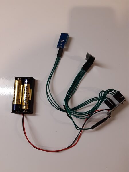
For my initial deployment I wanted to test the power usage of a sensor in the field so as to see if this approach is viable. This sensor would use a DHT11 temperature and humidity sensor along with the radio and would be powered from 2xAA batteries. I also built a simple serial gateway which I connected directly to my main server via USB.
The parts used in my build were as follows:
- an Arduino Pro Mini 3.3V (clone) for the sensor
- an (old) Arduino Duemilanove (but an Uno or Nano will also do) for the gateway
- 2xNRF24L01+ radio modules
- a DHT11 sensor (if you have to order one, buy a DHT22/AM2302 version for better accuracy)
- a 2xAA battery holder
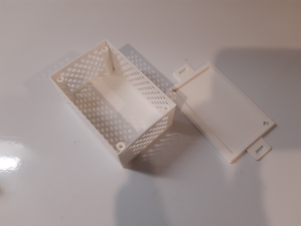
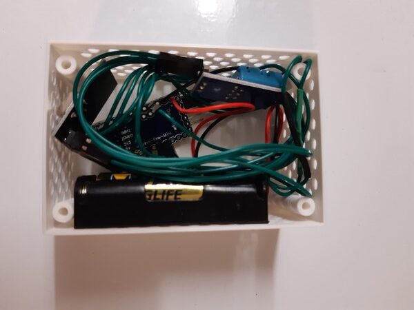
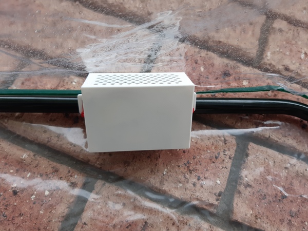
- This 3D printed case, with some custom dimensions. My updated OpenSCAD and STL files are in Gitlab.

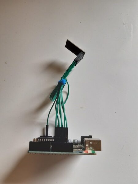
These were assembled pretty much as per the instructions. First I connected up the radios to both gateway and sensor. I then connected up the DHT sensor and the battery holder on the sensor side. It’s worth noting that I used digital pin 4 rather than pin 3 for the DHT because I connected it without looking at the instructions. However, it makes little difference, just a minor change to the example code.
I didn’t make any hardware optimisations for low power usage at this stage, except for the obvious one of removing the power LED on the pro mini board (LED1 on the schematic). This will save a significant amount of power, since otherwise it would be on all the time.
Software
The software side of things was even more trivial than the hardware. For the gateway I just flashed the provided serial gateway code. For the sensor I just flashed the DHT example code with the small modification to the pin noted above. Both of these just worked without any further tweaking. The DHT example did require me to include a custom DHT sensor library which I copied from the git repo in question.
I used my preferred tool of Platformio for building and flashing. The only things to consider here are to initialise the projects with the correct board names (diecimilaatmega328 and pro8MHzatmega328 in my case) and to install the MySensors library in each project. This can be accomplished with the command:
platformio lib install --save MySensorsIf you want to reproduce my exact setup or use it as a basis for your own, you can grab my code from GitLab.
Connecting MySensors to Home Assistant
With the firmware flashed to the devices, the next step is setting up the MySensors controller in Home Assistant. The first step in this process was making the serial adapter of the Arduino available through the layers of virtualisation in my setup. In order to do this I first added the serial adapter as a USB device to the KVM virtual machine via virt-manager. Secondly, I added the device to the Home Assistant container in my docker-compose.yml file with the entry:
devices:
  - /dev/ttyUSB0:/dev/ttyUSB0
Once the deployment had finished, I was able to add the MySensors integration to my Home Assistant configuration, which I did in a new package file:
mysensors:
   gateways:
     - device: /dev/ttyUSB0
       persistence_file: '/config/mysensors.json'
   debug: true
   persistence: true
   version: '2.3'
   optimistic: false
This sets up the integration with a single serial gateway on the port in question. With HASS restarted after this change, I was able to see my sensors. However, the entity IDs and resulting friendly names are based on the MySensors internal identifiers. I don’t really mind the cryptic entity IDs, but I updated the friendly names by adding the following to my customize section:
sensor.temperatureandhumidity_3_0:
friendly_name: "Greenhouse Humidity"

sensor.temperatureandhumidity_3_1:
friendly_name: "Greenhouse Temperature"
Notifications
The final step in the HASS setup for this achieves the goal of being notified when I need to check on the seedlings. This was accomplished via a couple of simple automations:
automation:
  - alias: "Greenhouse High Temperature Notification"
    trigger:
      platform: numeric_state
      entity_id: sensor.temperatureandhumidity_3_1
      above: 27
      for:
        minutes: 30
    condition:
      condition: state
      entity_id: input_boolean.greenhouse_active
      state: 'on'
    action:
      service: notify.family
      data_template:
        title: "Greenhouse Temperature High!"
        message: "The greenhouse temperature is {{ states.sensor.temperatureandhumidity_3_1.state }}{{ states.sensor.temperatureandhumidity_3_1.attributes.unit_of_measurement }}. You may wish to open the door and check if the plants need watering."
  - alias: "Greenhouse Low Temperature Notification"
    trigger:
      platform: numeric_state
      entity_id: sensor.temperatureandhumidity_3_1
      below: 11
      for:
        minutes: 30
    condition:
      condition: state
      entity_id: input_boolean.greenhouse_active
      state: 'on'
    action:
      service: notify.family
      data_template:
        title: "Greenhouse Temperature Low!"
        message: "The greenhouse temperature is {{ states.sensor.temperatureandhumidity_3_1.state }}{{ states.sensor.temperatureandhumidity_3_1.attributes.unit_of_measurement }}. You may wish to close the door."
These are pretty simple and send the notifications via my Gotify server. The only minor bit of complexity was that I added an input boolean to allow the notifications to be controlled together. I could just as easily turn off both automation rules when the greenhouse is not in use, but it’s nice to have a single switch for that purpose:
input_boolean:
  greenhouse_active:
    name: "Greenhouse In Use"
    icon: mdi:sprout
Range Issues
With all that in place, I tested the sensor overnight inside the house and then deployed it the following morning. I had placed it inside as close to the back wall where the greenhouse is located as possible and it worked fine. It even worked fine after deploying it in the greenhouse for around 12 hours.
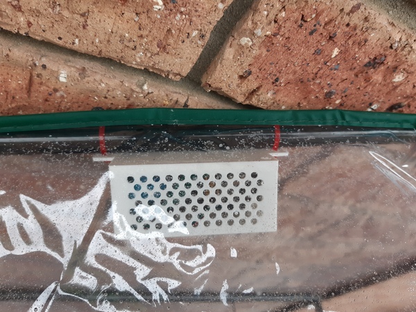
Then it stopped sending data.
I brought the sensor in and examined it. The battery voltage was fine and after a reset it came back up, so I deployed it again. The same thing happened within a few minutes. I then brought the sensor back inside and put it in the garage, just a few meters from the gateway. It’s been operating there successfully for several days.
I can only conclude from this that the radio range is pretty poor. I have a couple of mitigations in mind for this, the first of these will be to move the gateway closer to the garden. For this I may need a networked gateway, or I may plug it into a nearby Raspberry Pi. I’ll try the Raspberry Pi idea first and see if I can get it working with the Node-RED MySensors nodes. Ideally, I’d like these just to operate as a proxy so that the MySensors controller will still be Home Assistant.
The other potential mitigation is to use a radio with a higher gain antenna and amplifier on the gateway. I may do this anyway in time in order to get better range into the garden for other sensors.
Conclusion
Overall I’m pretty pleased with the MySensors setup I’ve been able to create here. It’s very much a prototype and there are still a few issues to work out, but it’s promising. The best thing is that it only took me a couple of hours, though this was aided massively by having the parts already to hand.
MySensors itself seems quite nice and there is certainly a large community around it. As compared to other offerings such as ESPHome, it feels a bit basic to actually have to write (or copy) Arduino code and upload it to the device. I much prefer the YAML approach for describing simple sensors. That said, I still had to write no code in order to get this working! I’d love to see a similar YAML based code generator for this platform though.
I’ll definitely be building and deploying a few more MySensors nodes, primarily in the garden where ability to run off batteries for a decent length of time is a great advantage. However, I need to fix the range issue first, which I’ll be sure to post an update on.
As always please get in contact to share your own experiences!
Leave a Reply