This post is part of a series on this project. Here is the series so far:
Looking back, it seems to have been a ridiculously long time since my last room sensor post. It’s well over a year, but it doesn’t seem that long ago. This project has been majorly delayed by a few issues and generally hasn’t been top of my todo list. However, I’m now at the point where I have the prototype sensor installed and working. Actually, it’s been working for several months, but I hadn’t got around to writing it up! In this post I’ll mostly be detailing the infrastructure used to get power to the sensor. There will also be some discussion on the case and mounting as well as a few words on the software.
Finding a Case
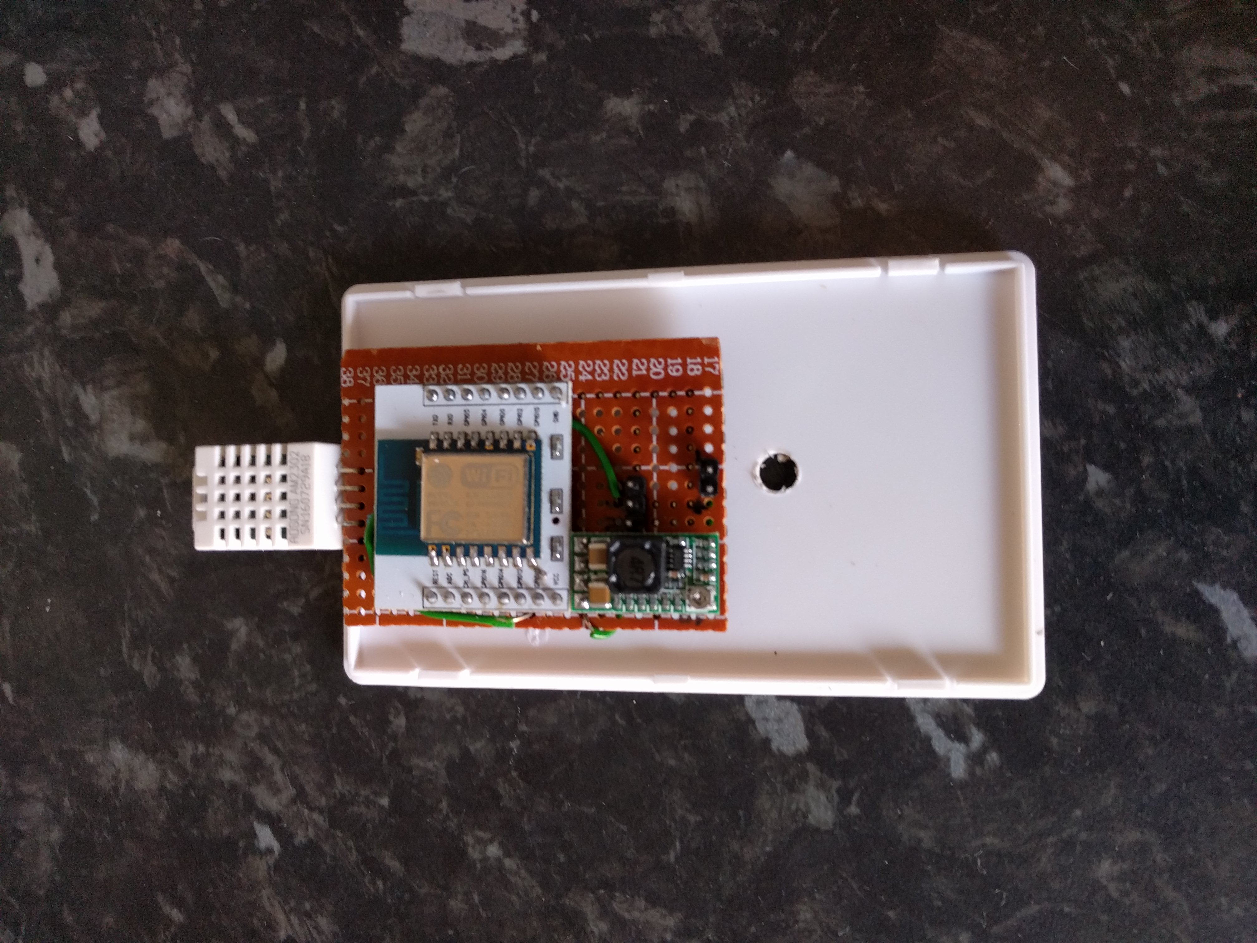
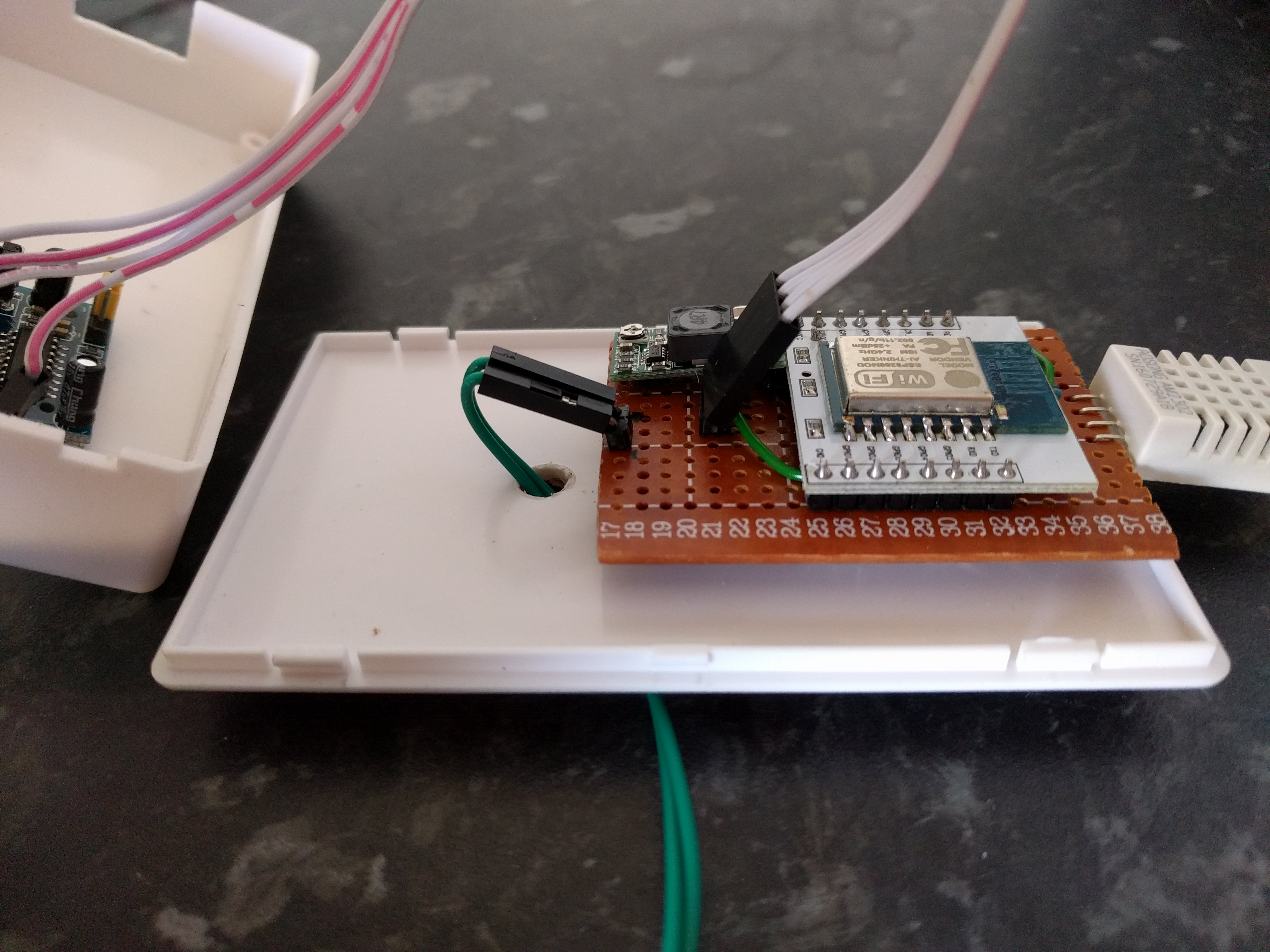
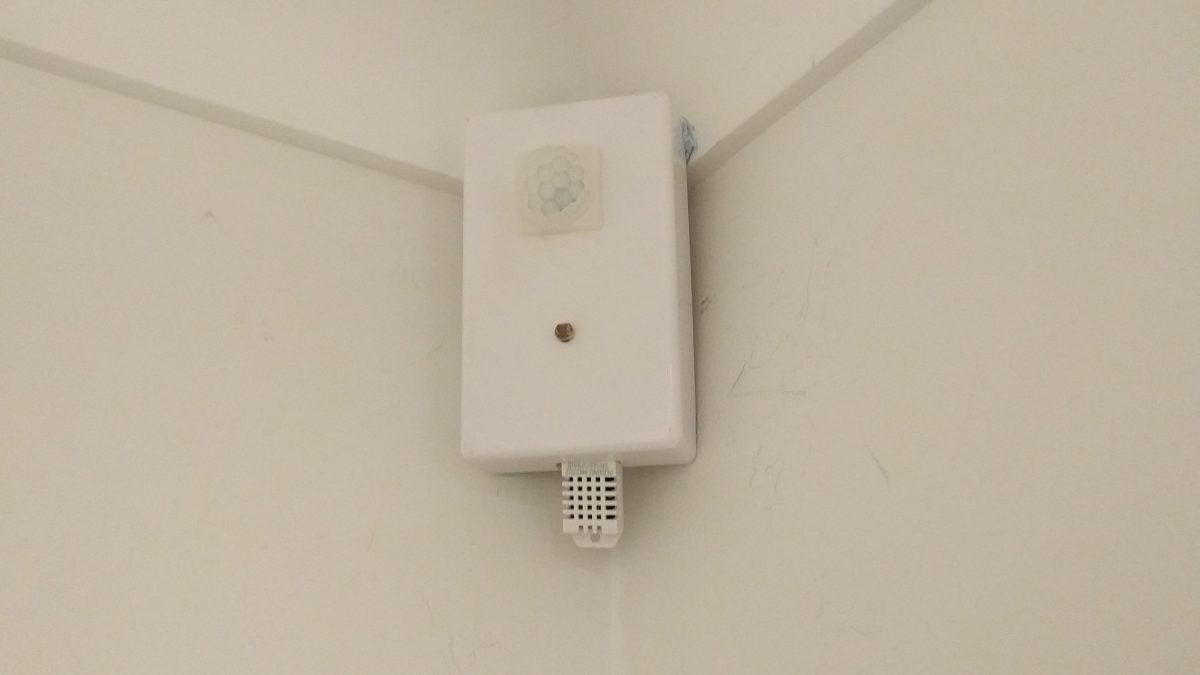
It would have been really nice just to 3D print a case and mounting bracket for the sensors. Unfortunately, I don’t (yet) have a 3D printer and it was cheaper to buy cases than to get a 3D printing service to print them. I settled on a 100x60x25mm case and ordered 15 of them. Once they arrived I was able to fit all the electronics inside and cut a slot in the bottom for the DHT22 sensor. A dremel-like tool would have helped a lot here, but I managed to do it manually and it looks OK. I actually reversed the case so that the lid became the rear as this looks a little nicer and helped with the mounting of the components.
I also fitted a light sensor based on an LDR voltage divider circuit to the front of the case. Unfortunately I had issues with the ADC pin on the bare ESP8266 module I used for the prototype. It’s odd because I’ve had this working with the Wemos D1 modules before (which have their own voltage divider on the input also). In the end I didn’t manage to get this working and have resolved to replace the prototype board with a Wemos based one when I do the sensors for the rest of the house.
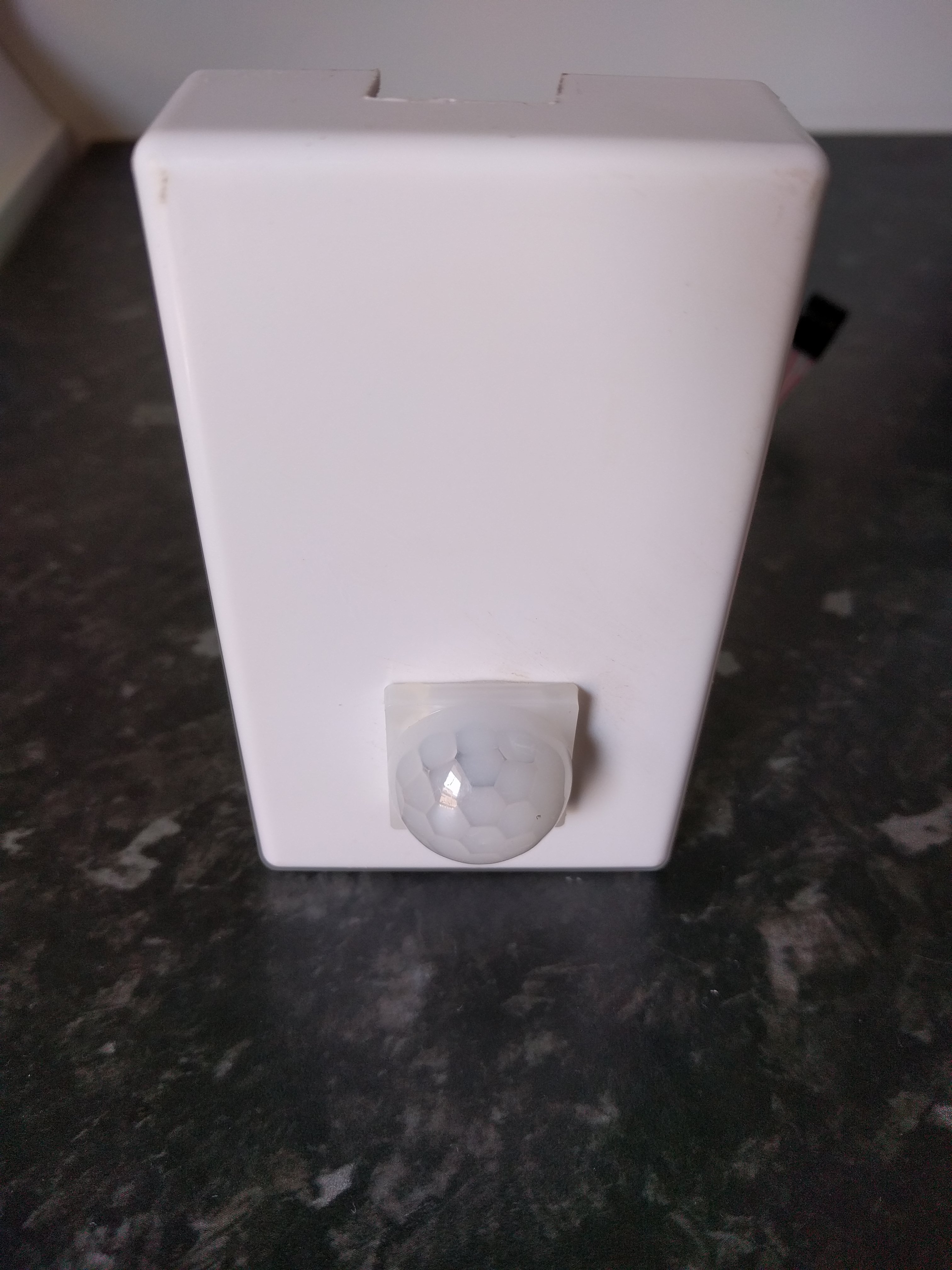
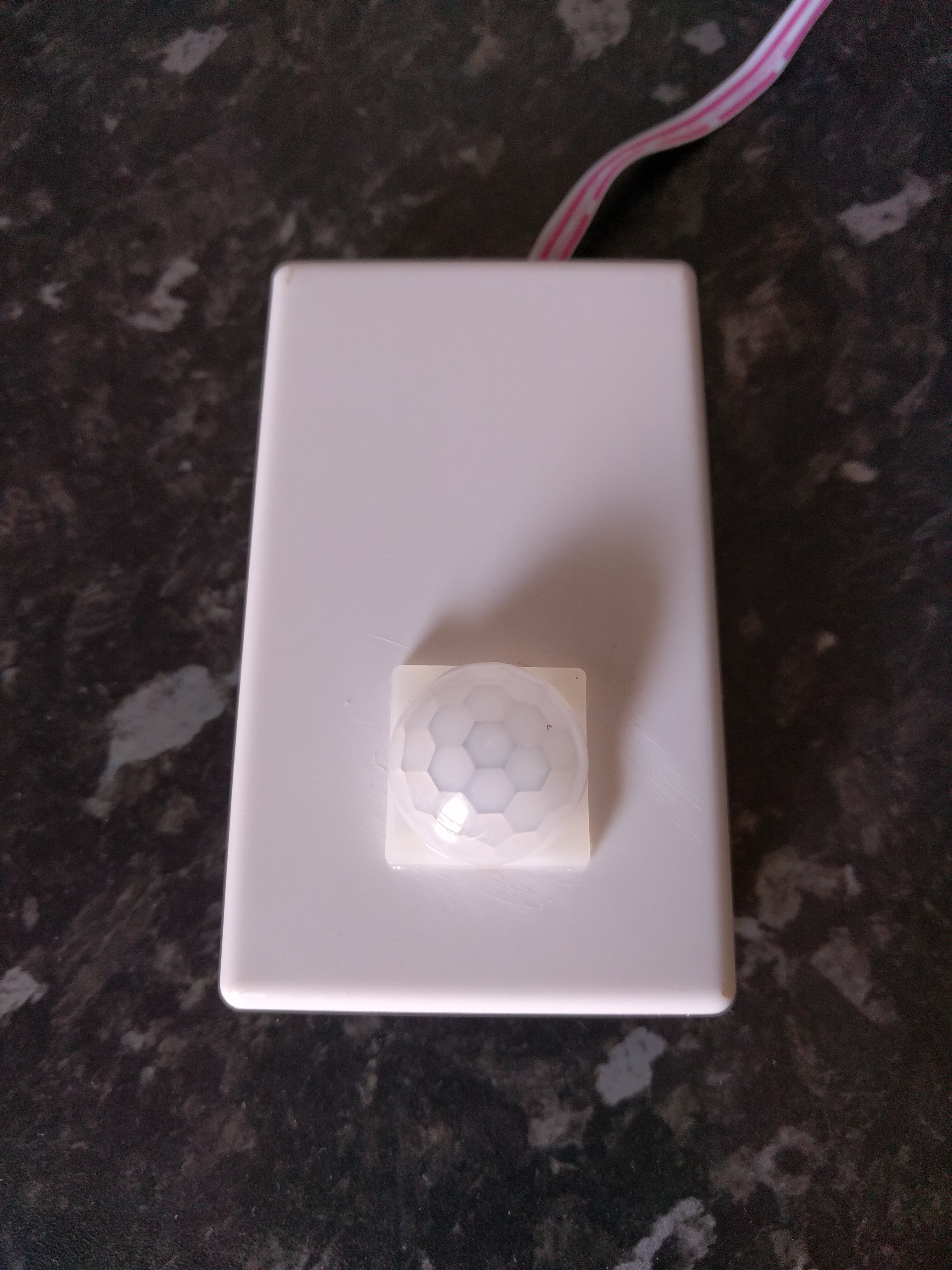
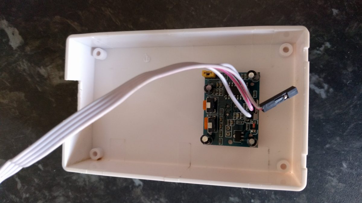
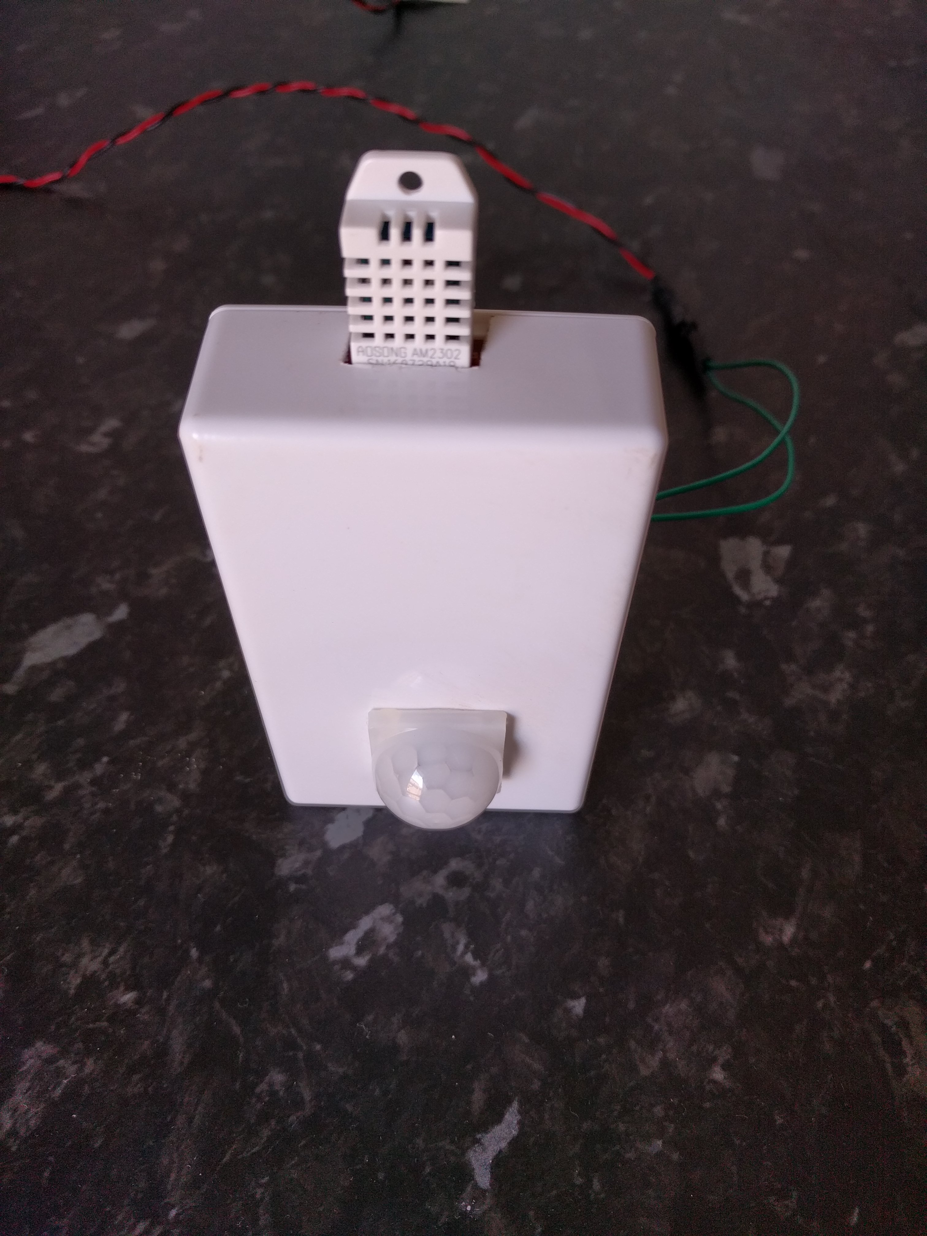
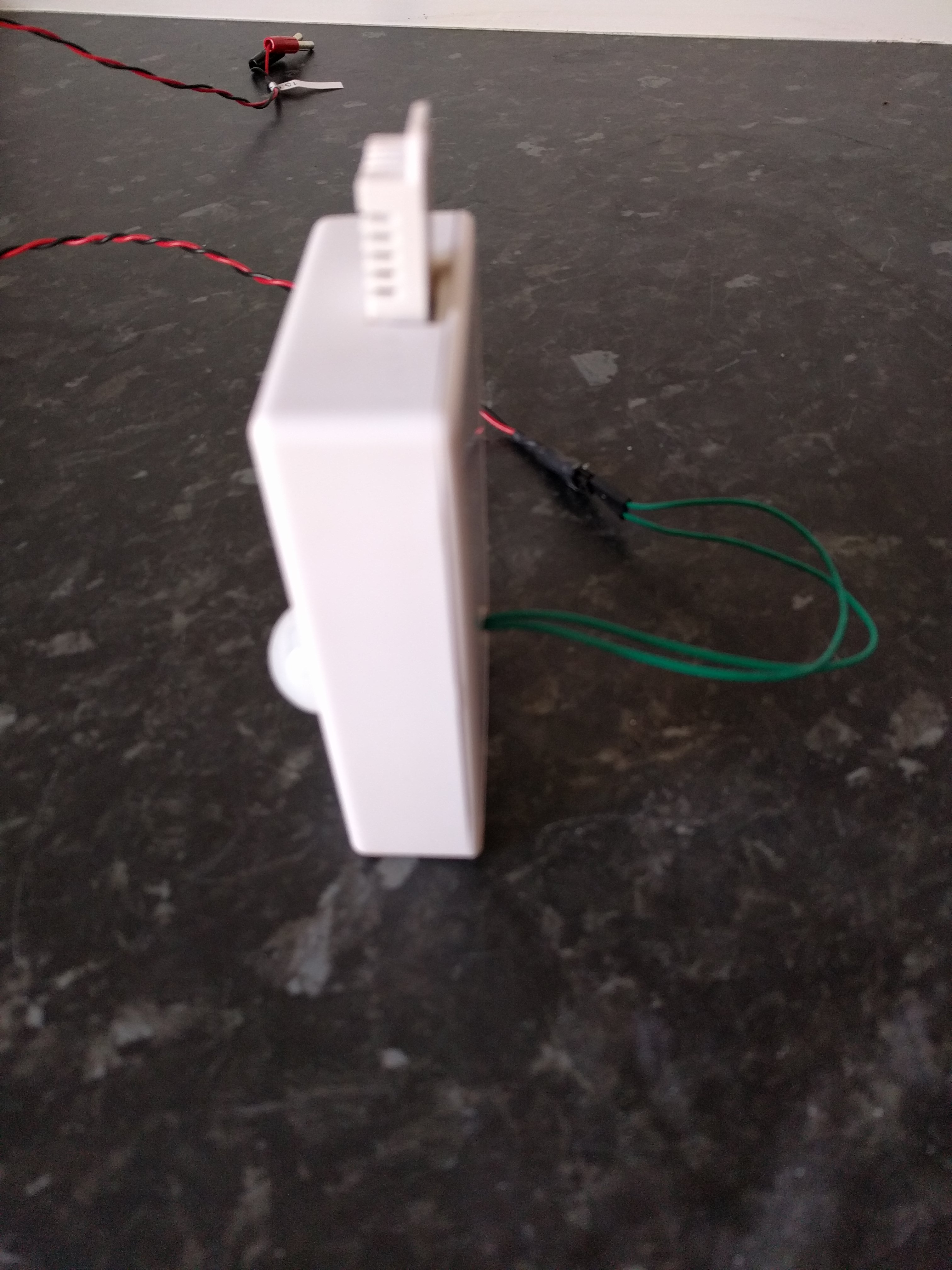
I drilled a hole in the front of the case for the PIR sensor and mounted the diffuser over the hole. The PIR board itself was hot glued to the reverse of this. This works really well – in fact if anything the sensor is a little too sensitive. I need to tweak the pots a little to dial this down.
You can see pictures from during the assembly as well as the fully assembled case below:
Power Setup and Wiring
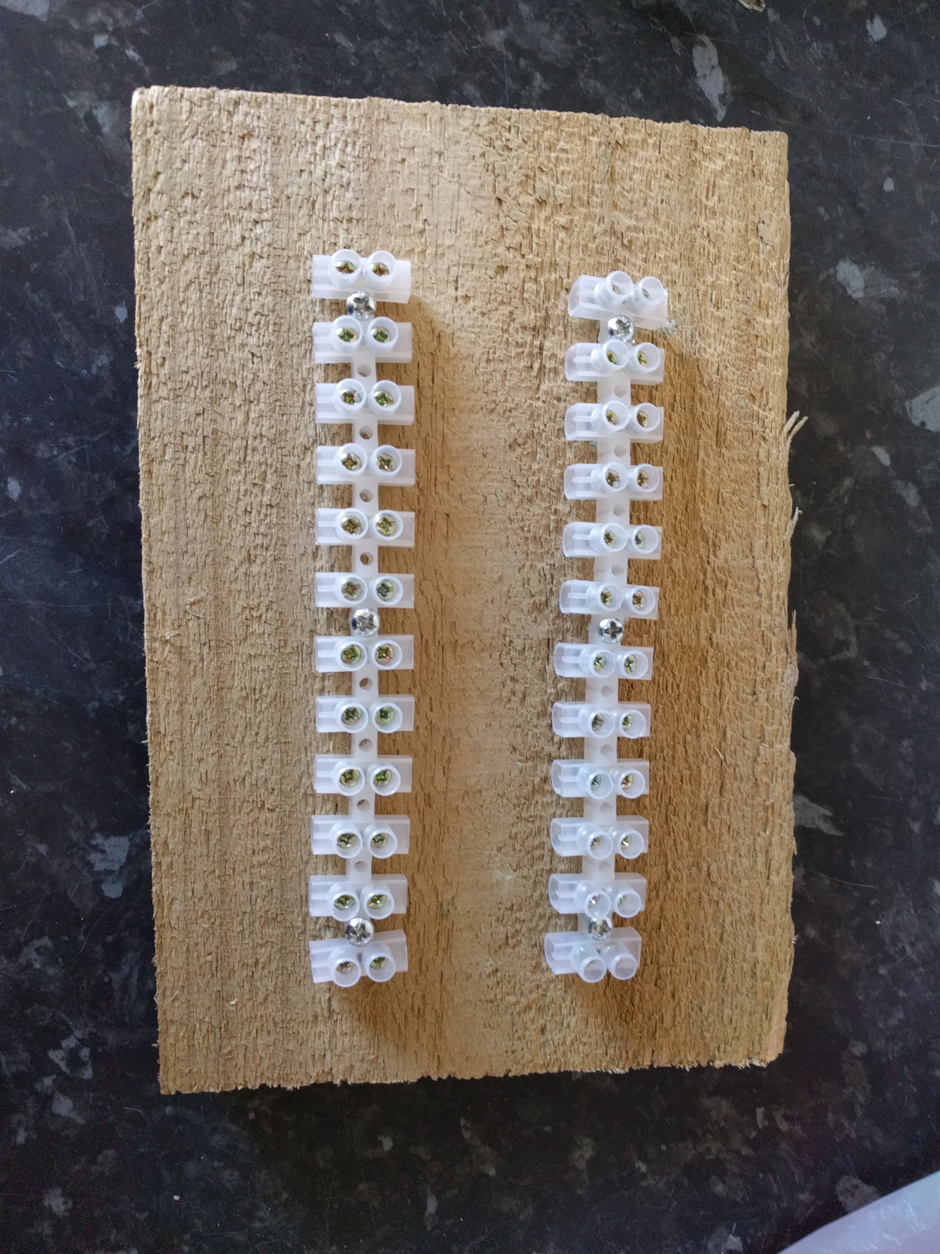
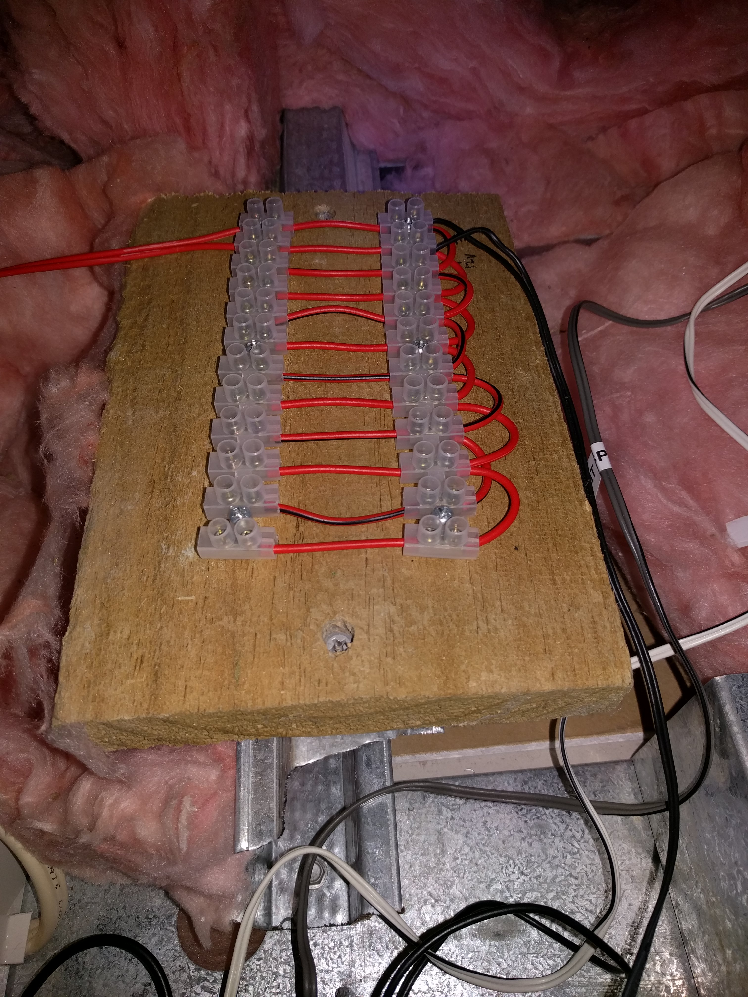
In order to get power to the sensors I had decided on running 12V lines through the roof space of the house. These would then come down through the ceilings in the corner of each room for the sensors. The cables would be fed from a central distribution board mounted near the loft hatch in the ceiling. Since the power requirements for the 12 sensors I wish to eventually install are minimal a single 2A is enough to power the whole lot with some room to spare. Some pictures of the distribution board (before and after installation) are shown below:
I had initially wanted to mount the power supply down in the ‘server rack’ and run the power up through an (existing) whole in the wall to the loft. However, after an abortive attempt at running a cable through the wall (in which I was foiled by pesky insulation and there was much swearing), I eventually came to the conclusion that mains power was needed in the roof space.
Time passes…
It took a while to really commit to and allocate funds to this option. Eventually the electrician came and installed four shiny new power points in the roof space just next to the loft hatch. Four power points is obviously overkill for this project. However, in the intervening time some other projects had come up for which the remaining plugs would be useful.
Once the power points were in place I ran the cabling for the 12V line to the room in which the sensor was to be installed and connected it all up. As if by magic power flowed and the sensor sprung into life! (barring various frustrating issues with loose connections).
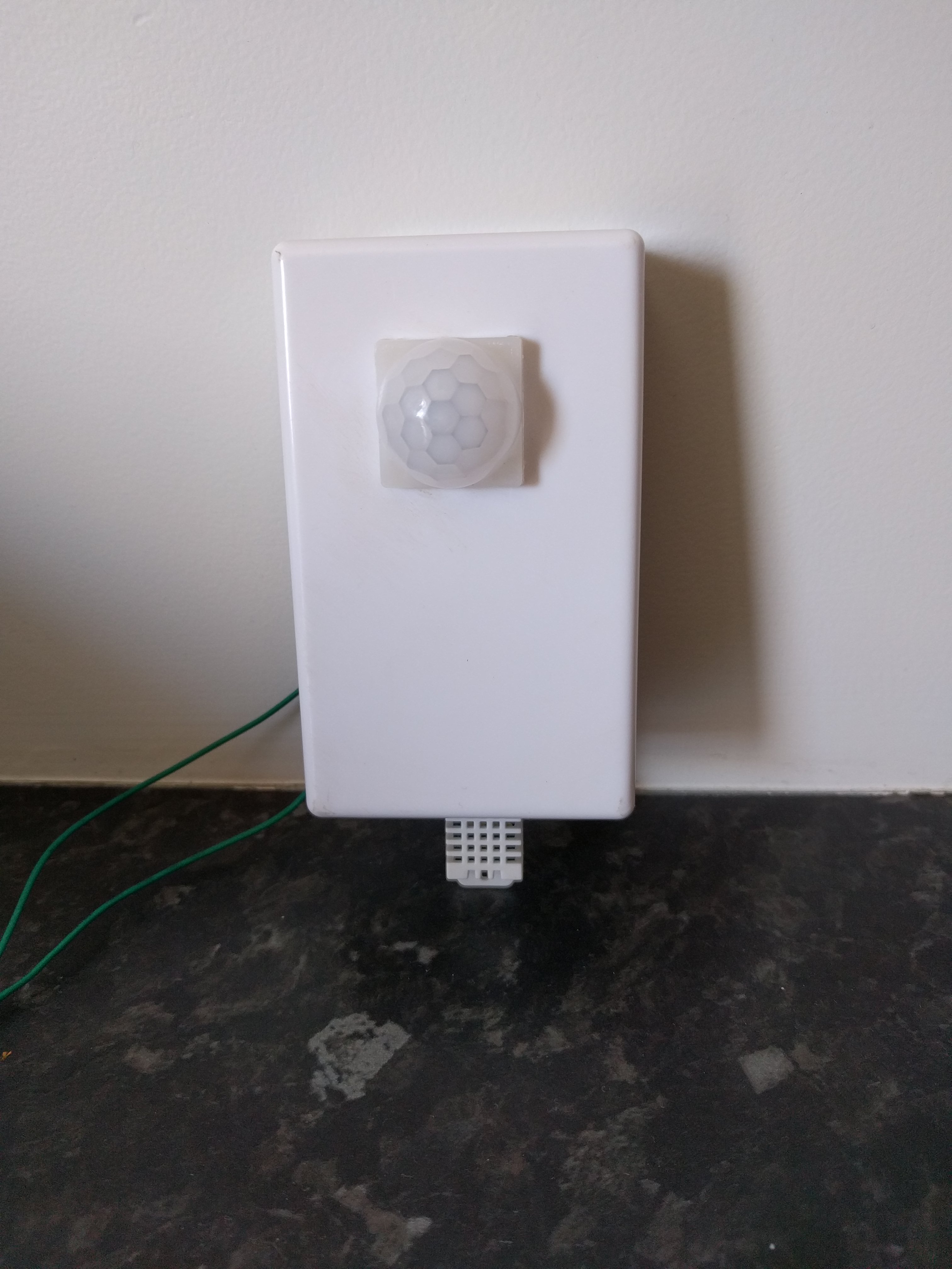
I had quite an interesting time working out how to mount the sensor in the corner of the room. I initially stuck it up with 3M double sided sticky pads, but ended up pulling it up and down several times so that I ran out of these. Eventually I opted for good old fashioned blu-tack as a temporary solution! I’m intending to replace this with a 3D printed bracket which will fit the oddly shaped space between the case and the wall. This will allow the sensor to be attached much more permanently. However, for now the blu-tack does the job and proves the concept.
Relay Power Control
I mentioned above that I had installed several extra power sockets in the roof space for other projects. One of those other projects required putting a Raspberry Pi in the roof space. The other project is now completed and I’m hoping to document it soon. For this I pressed into duty my old Raspberry Pi Model B (the one with 512Mb of RAM). Although old, this hardware is sufficient for running a small Node-RED instance as well as performing it’s other intended duty.
This gave me a nice way to control the power supply to the room sensor distribution board and hence all the sensors. That meant that if a sensor were to go offline I could cycle the power remotely without having to climb up in the roof space. To do this I inserted a relay into the power 12V line between the power supply and the power distribution board.

I connected this to the normally closed input of the relay so that the relay must be switched on to kill the power. The state is then inverted in Node-RED. In this way the switch in Home Assistant shows as on most of the time. I only had 5V relays sitting in my parts box. So, I soldered up a quick transistor circuit on a breadboard to allow me to drive the relay from the 3.3V logic of the Pi. Doing this is left as an exercise for the reader, since I forgot to document what I built!
Driving the Relay in Node-RED
To drive the relay I use a variation of my MQTT discovery switch in Node-RED. This is implemented via the following flow:
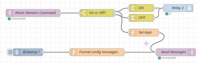
The JSON for this is shown below (copy it and import into Node-RED):
[{"id":"e683c60f.71219","type":"tab","label":"Room Sensors","disabled":false,"info":""},{"id":"49f1f109.608fa","type":"rpi-gpio out","z":"e683c60f.71219","name":"Relay 2","pin":"13","set":true,"level":"0","freq":"","out":"out","x":760,"y":60,"wires":[]},{"id":"80843251.fcdf58","type":"mqtt in","z":"e683c60f.71219","name":"Room Sensors Command","topic":"homeassistant/switch/room_sensors/cmd","qos":"2","broker":"65d3656f.217c14","x":170,"y":80,"wires":[["afc07304.5d321"]]},{"id":"afc07304.5d321","type":"switch","z":"e683c60f.71219","name":"On or Off?","property":"payload","propertyType":"msg","rules":[{"t":"eq","v":"ON","vt":"str"},{"t":"eq","v":"OFF","vt":"str"}],"checkall":"false","repair":false,"outputs":2,"x":430,"y":80,"wires":[["a2b8666b.9e744","6c973ed5.7607f8"],["76f0cbf9.50415c","6c973ed5.7607f8"]]},{"id":"a2b8666b.9e744","type":"change","z":"e683c60f.71219","name":"ON","rules":[{"t":"set","p":"payload","pt":"msg","to":"0","tot":"str"}],"action":"","property":"","from":"","to":"","reg":false,"x":610,"y":60,"wires":[["49f1f109.608fa"]]},{"id":"76f0cbf9.50415c","type":"change","z":"e683c60f.71219","name":"OFF","rules":[{"t":"set","p":"payload","pt":"msg","to":"1","tot":"str"}],"action":"","property":"","from":"","to":"","reg":false,"x":610,"y":100,"wires":[["49f1f109.608fa"]]},{"id":"d673854.bac6478","type":"mqtt out","z":"e683c60f.71219","name":"Send Messages","topic":"","qos":"2","retain":"true","broker":"65d3656f.217c14","x":750,"y":240,"wires":[]},{"id":"95bdf49b.5a011","type":"function","z":"e683c60f.71219","name":"Format config messages","func":"var config = {\n payload: {\n name: \"Room Sensors\",\n command_topic: \"homeassistant/switch/room_sensors/cmd\",\n },\n topic: \"homeassistant/switch/room_sensors/config\"\n};\nreturn config;","outputs":1,"noerr":0,"x":430,"y":240,"wires":[["d673854.bac6478"]]},{"id":"c45bb370.032b48","type":"inject","z":"e683c60f.71219","name":"@Startup","topic":"","payload":"","payloadType":"date","repeat":"","crontab":"","once":true,"onceDelay":"3","x":150,"y":240,"wires":[["95bdf49b.5a011"]]},{"id":"6c973ed5.7607f8","type":"function","z":"e683c60f.71219","name":"Set topic","func":"msg.topic = \"homeassistant/switch/room_sensors/state\";\nreturn msg;","outputs":1,"noerr":0,"x":620,"y":160,"wires":[["d673854.bac6478"]]},{"id":"65d3656f.217c14","type":"mqtt-broker","z":"","name":"Home Broker","broker":"mybroker.example.com","port":"1883","clientid":"","usetls":false,"compatmode":true,"keepalive":"60","cleansession":true,"birthTopic":"","birthQos":"0","birthPayload":"","closeTopic":"","closeQos":"0","closePayload":"","willTopic":"","willQos":"0","willPayload":""}]Over the following months of usage, I noted several (infrequent) instances where the sensor stopped responding. In these cases it needed a manual (though remote controlled) power cycle. In order to automate this and so reduce downtime, I wrote the following Home Assistant automation:
  - alias: Auto-reset Room Sensors
    trigger:
      - platform: state
        entity_id: binary_sensor.prototype_sensor_status
        to: "off"
        for: "00:10:00"
    action:
      - service: switch.turn_off
        entity_id: switch.room_sensors
      - delay:
          seconds: 30
      - service: switch.turn_on
        entity_id: switch.room_sensors
      - service: notify.notify
        data_template:
          title: "Room Sensors Reset"
          message: "Device '{{ trigger.to_state.name }}' was offline for 10 minutes, room sensors reset."
Basically, this will trigger after the sensor has been offline for 10 minutes. Once triggered it will turn the sensor off and on again (with a 30 seconds delay in between). It will also send a notification to inform me that this has happened. I think this has been triggered twice and as a result the sensor hasn’t been unavailable for any length of time.
Software Changes
Since installing the prototype sensor, I haven’t actually been running my Micropython Room Sensor software on it. Instead I’ve been trying out ESPHome on this and another project, since it’s been getting a lot of attention in the HASS community recently. I specifically wanted to see if ESPHome was an easier/maintenance free option for these types of projects.
My take away from this is that ESPHome is really nice and very easy if you don’t want to do anything complicated. If all you have are a few sensors or actuators that you want to connect, it’s great! In fact it’s almost perfect for this kind of project. You can even do some moderately complicated data conversions and on device automation using the lambda syntax. For this reason, I’d put it in the same basket as the likes of ESPeasy. Although it has some advantages in comparison to other systems, especially if you are already running Home Assistant. Kudos to Otto Winter for coming up with such a great piece of software!
However, it does get more difficult when you want to more complicated things. I ran into some of these issues in my other project, which I’ll detail when I eventually write it up. For now ESPHome gets my wholehearted recommendation.
ESPHome Configuration
I especially like that since the configuration for ESPHome devices is just YAML it’s really easy to store in git. I haven’t got a cleaned up git repo for my projects ready to publish. However, since the configuration for this project is so simple, I can post the whole thing here:
esphome:
  name: room_sensor_prototype
  platform: ESP8266
  board: esp12e

wifi:
  ssid: 'my-wifi'
  password: 'supersecret'

mqtt:
  broker: 'mqtt.example.com'
  username: 'test'
  password: 'supersupersecret'

# Enable logging
logger:

ota:
  password: 'massivelysupersecret'

sensor:
  - platform: dht
    pin: 12
    model: AM2302
    temperature:
      name: "Test Temperature"
    humidity:
      name: "Test Humidity"
    update_interval: 15s

binary_sensor:
  - platform: status
    name: "Prototype Sensor Status"
  - platform: gpio
    pin: 2
    name: "Test Motion"
    device_class: motion
You’ll notice that I’m still using the MQTT transport rather that the native API component with the Home Assistant ESPHome component. This is mainly because I built this before the native API was released and I didn’t need to update it. I understand there are some advantages to using the native API, so I probably will try it at some point, especially if I want to try an esp-cam project.
What’s Next
So far, I’m really happy with the performance of the sensor. I’ve been using it in a few automations which I’m intending to detail in a further post. The next thing to do is build further sensors for the remainder of the house. In order to make this less error prone I’ve decided to design an adapter PCB in Kicad for the Wemos D1 Mini clones I’ve been using in other projects. This will get me away from the fiddling with bare ESP modules and hopefully mean that the light sensor will work.
As mentioned above, I also want to design a 3D printed bracket to fit the oddly shaped space in the corner behind the sensor. This will have to wait until I get a 3D printer, which will hopefully happen later this year.
Aside from that the only other job will be deploying the new sensors once they are built. This will mean running all the remaining power cables through the roof space, so lots of crawling around up there (yay! /s).
Leave a Reply