The primary form of heating in our home is a wood burning stove. You’re probably thinking that this isn’t very ‘smart’ and you’d be right. It’s the least smart part of my smarthome, requiring daily lighting and monitoring during the winter months. What it is though is eco-friendy and cheap to run. Also, nothing quite beats a wood fire for warmth and hygge. The point of all this is that we have a wood shed (two actually) at the back of our house. During dark winter nights, trips to these have been fraught with danger and mystery due to a lack of lighting. That is until now: this winter my completely over-engineered, ESP32 driven, solar powered, smart LED lights will light the way!
Of course, I could just use a head torch for my after dark trips to the wood shed. Or buy any number of (doubtless cheap and nasty) solar powered lights from the local DIY store. However, that didn’t seem very fun and wouldn’t integrate with Home Assistant and the rest of my smarthome.
Components
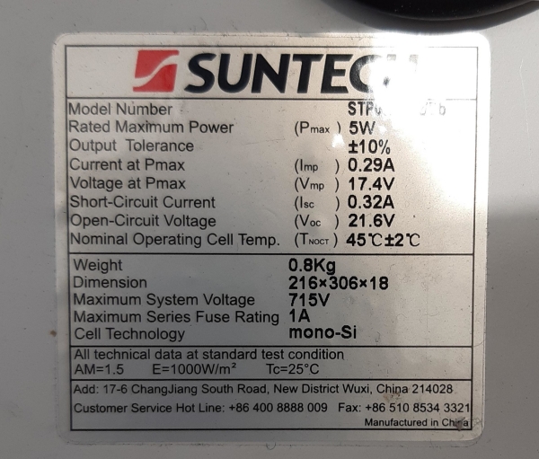
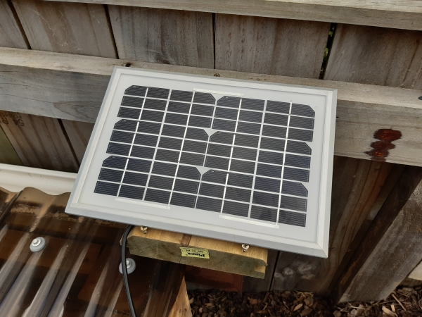
For these lights I decided to use WS2812B light strip driven by an ESP32. The solar power system would utilise an off the shelf solar controller and lead acid battery along with a 5W solar panel which I acquired cheap from work.
Full Parts List
- An ESP32 development board (I used the DOIT board, but pretty much any ESP32 board will do);
- 1x 5A adjustable power supply, which will be set to 5V for the LED strip;
- 2m of IP67 rated WS2812B light strip;
- 1x single channel relay board;
- 1x 20A solar controller;
- 5W solar panel (since I acquired this from work I don’t have a specific panel to recommend);
- Various resistors for the power monitoring circuits;
- A DHT22/AM2302 temperature/humidity sensor;
- IP65 rated electronics case (this was mine, but you should search around to find one that will fit your electronics);
- 1x IP68 PG9 cable gland (comes as a pack of 10, but very useful to have around)
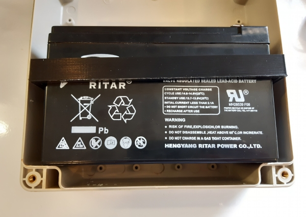
- 1x 7Ah lead acid battery (I acquired mine from a local supplier, so I don’t have a link to share);
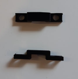
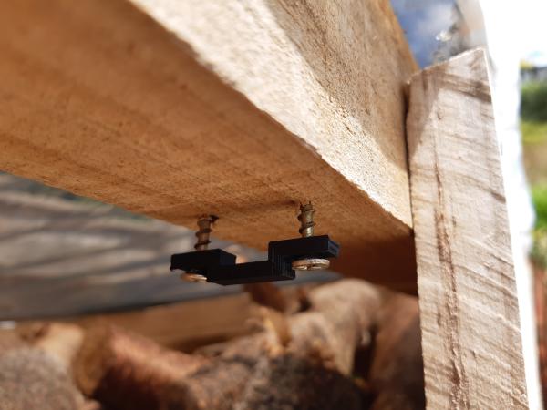
- 10-15 of these 3D printed U-brackets (based on this design);
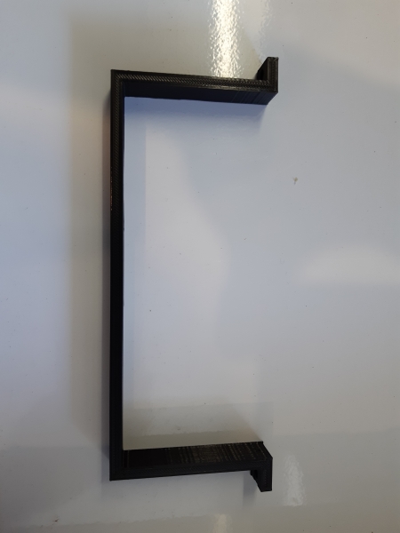
- A larger U-bracket for holding the battery (I actually printed this slightly too large and had to trim down the sides);
- Various screws, cable ties, double sided tape and heatshrink tubing;
- Clear roofing sealant for sealing cable joins;
- Several meters of speaker wire.
GCode for the Ender 3 is also available for the 3D printed parts. If you have another printer you’ll need to slice the STL files yourself. I had a few issues with some of the small brackets adhering to the bed, but I was able to get a high enough yield thanks to the OctoPrint-Cancelobject plugin.
The charge controller is rather over-spec’d for the LEDs I’m actually running (which pull less than 2A at the 12V battery voltage, on full brightness). This is because I originally thought I would use the full 5m of LED strip that I ordered. However when it arrived and I saw how bright they are I downgraded to just 2m. I had also ordered a beefier power supply for this purpose. The one I ended up using was left over from my failed tablet salvaging efforts. This means I have 3m of LED strip and a decent power supply left over for a future project.
Putting it Together
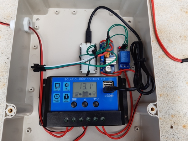
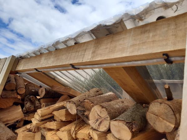
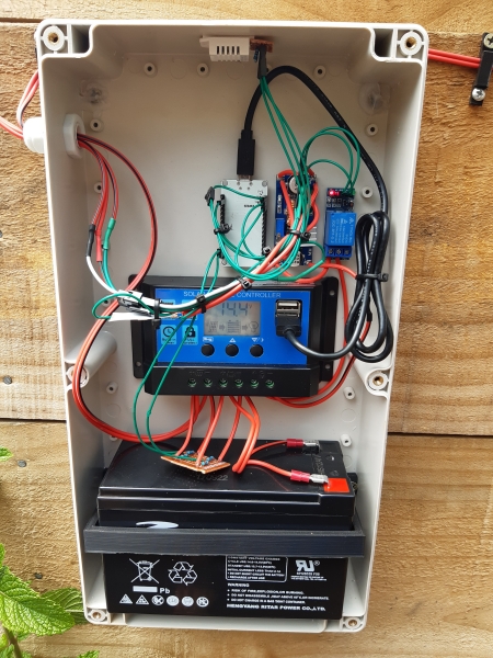
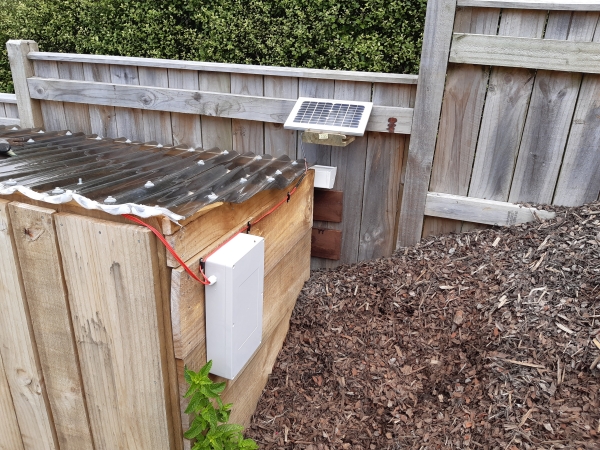
I spent the better part of a day putting together the components and soldering all the cabling. I then spent at least another day mounting things on the shed and fixing issues. All the joins between cables are double covered with heatshrink tubing. The first layer insulates the cable from any neighbouring cables. The second layer is for waterproofing and has roof sealant injected into it. The same is done on the joins between the cable and the LED strip. Hopefully this will stand up to the intense New Zealand rain. Seriously, you have not seen rain until you’ve seen NZ rain! Luckily most of the components are mounted out of the worst of the weather. The cables enter the box through the IP68 cable gland which should be weather tight.
When I tested the LEDs after soldering the lead out wires to them I found that the colours were off and transitions and effects were flickery. This could have been due to either a power issue or an issue on the data line. Measuring the 5V line showed minimal voltage drop there. Since the LEDs were OK before adding the lead out I went with the data issue.
The issue turned out to be due to voltage drop on the 3.3V signal from the ESP32 along the lead out cable. The data line is quite sensitive to voltage drop here because the LEDs are supposed to receive a 5V data signal. They work with 3.3V, but not much lower. In order to solve this I added an single extra pixel at the microcontroller end to boost the signal voltage from 3.3V to 5V. This solves the issue since the data signal is being amplified by each pixel in the chain.
ESPHome Code
The ESPHome code to drive the lights is fairly simple. First we start with the standard setup:
---
esphome:
  name: shed_lights
  platform: ESP32
  board: esp32doit-devkit-v1

wifi:
  ssid: !secret wifi_ssid2
  password: !secret wifi_passwd2
  use_address: !secret shed_lights_ip

mqtt:
  broker: !secret mqtt_broker
  username: !secret mqtt_user
  password: !secret mqtt_passwd

# Enable logging
logger:

ota:
  password: !secret ota_passwd
Here we define the board type, set up the wifi and MQTT connections, enable logging and set up OTA updates. If you’re wondering why I’m using MQTT rather than the ESPHome API, it’s for no other reason than I like MQTT!
power_supply:
  - id: 'led_power'
    pin:
      number: GPIO25
      inverted: true
Next I set up a power supply component. This is used along with the single channel relay to automatically power up and down the power supply to the LEDs. This will save a bit of power and also makes sure that there is no power flowing in the cables outside the box for most of the time, which may help in the event of a leaky connection. In order to do this I’m not running the ESP32 from the same 5V supply, instead using one of the USB ports from the solar controller.
The LED strip configuration is then pretty standard:
light:
  - platform: fastled_clockless
    chipset: WS2812B
    pin: GPIO23
    num_leds: 61
    rgb_order: GRB
    name: "Shed Lights"
    effects:
      - addressable_rainbow:
      - addressable_color_wipe:
      - addressable_scan:
      - addressable_twinkle:
      - addressable_random_twinkle:
      - addressable_fireworks:
      - addressable_flicker:
    power_supply: 'led_power'
Note that there are 61 pixels here, that 2m at 30 pixels per meter plus one sacrificial voltage boosting pixel. The addition of the effects is a bit of a gimmick since I’m mostly interested in white light for the application. I only bought the RGB LEDs because the price difference wasn’t enough to justify only buying white.
Voltage Sensing and Health Monitoring
After putting all this together and mounting it on the shed I decided that I’d like to have some form of monitoring for the voltages from the battery and solar panel. The solar controller obviously monitors these but there is no way to get this data out.
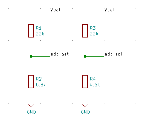
In the end I soldered up a couple of voltage divider circuits and added these to the setup in the box. I also added a DHT22 sensor for temperature and humidity sensing inside the box.
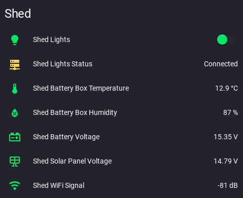
The ESPHome configuration for these follows. I also added a binary status sensor and a WiFi signal sensor to allow me to monitor the system remotely.
binary_sensor:
  - platform: status
    name: "Shed Lights Status"

sensor:
  - platform: wifi_signal
    name: "Shed WiFi Signal"
    update_interval: 180s
  - platform: dht
    pin: GPIO15
    model: AM2302
    temperature:
      name: "Shed Battery Box Temperature"
    humidity:
      name: "Shed Battery Box Humidity"
    update_interval: 180s
  - platform: adc
    pin: GPIO39
    name: "Shed Battery Voltage"
    icon: "mdi:car-battery"
    attenuation: "11db"
    filters:
      - multiply: 4.24
      - sliding_window_moving_average:
          window_size: 12
          send_every: 12
    update_interval: 15s
  - platform: adc
    pin: GPIO36
    name: "Shed Solar Panel Voltage"
    icon: "mdi:solar-panel"
    attenuation: "11db"
    filters:
      - multiply: 5.73
      - filter_out: 0.00
      - sliding_window_moving_average:
          window_size: 12
          send_every: 12
    update_interval: 15s
The voltage readings I am getting from the two voltage sensors are a little weird. The battery voltage is higher than I would expect and the solar panel voltage is lower. I double checked the multiplication factors against the raw ADC readings and the resistors used and the readings make sense. Initially I thought this could be due to the temperature inside the box (~50°C when it’s in full sun!), but now I’m not so sure since this is also the case at lower temperatures. It could be the behaviour of the charge controller. I’ll continue to monitor it over different charge states.
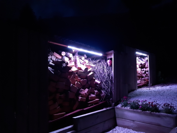
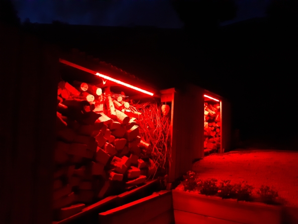
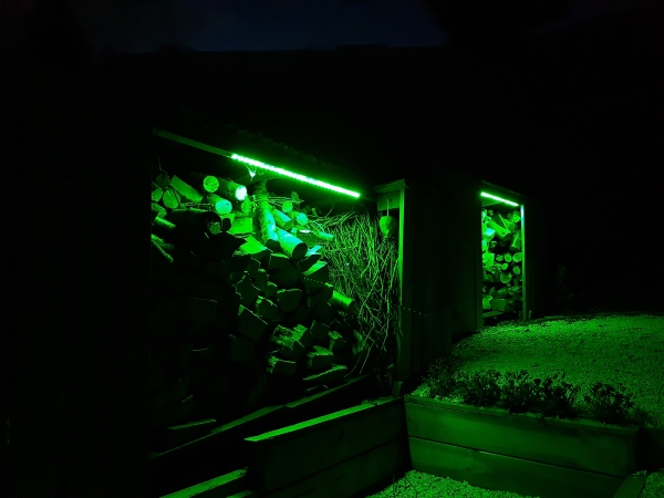
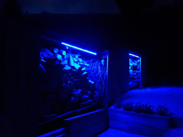
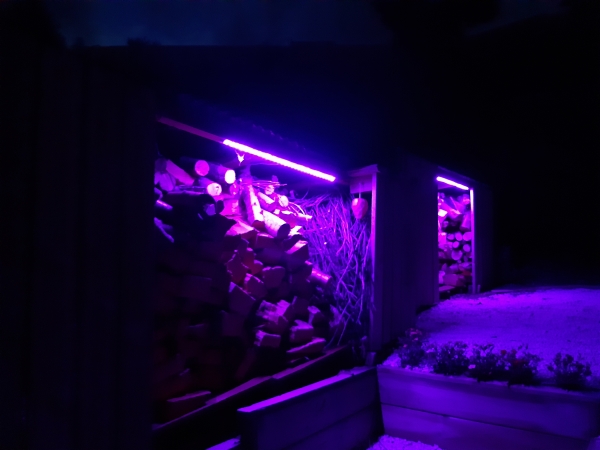
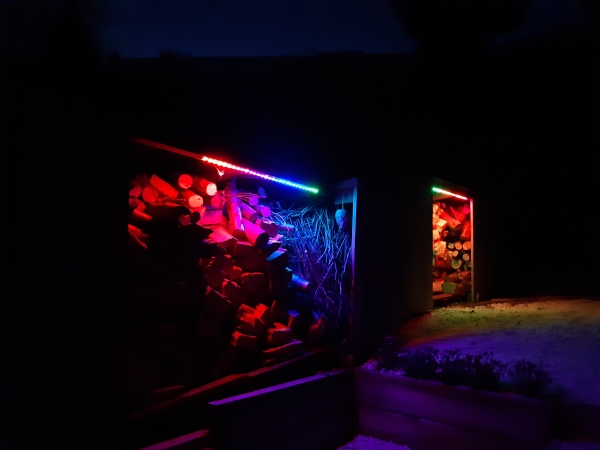
The Finished Product
Now the moment you’ve all been waiting for – gratuitous photos of the LEDs in fancy colours!
Conclusion
This is actually my first time using the WS2812B LED strip and I have so say I’m really impressed. You can be sure there will be other LED lighting projects coming in future now that I’ve dipped my toes in!
I’m really pleased with the final product. The LEDs look awesome and provide ample light for their task. The ESPHome base has so far been rock solid in terms of stability, which is what I’ve come to expect from using it in other projects.
The initial intention was to make these lights motion activated. However, I couldn’t find a motion sensor which was suitable for outdoor use. I’d also have to locate the sensor at the other end of the sheds from the battery box which would mean a whole load of wiring. As such I’ve decided to build by own wireless outdoor motion sensor and connect it to my MySensors network. I’ll then trigger the LEDs via an automation in Home Assistant. I’ll post an update on this when I have it running.
This has been a really fun and interesting project. As always, please let me know what you think in the feedback channels and feel free to share your own LED lighting projects.
Leave a Reply